Pearlie Bild1951

Speedometer Calibration How Many Mph Does One Speedo Gear Tooth Make UPDATED

Speedometer Calibration How Many Mph Does One Speedo Gear Tooth Make

  • Forums
  • Drivetrain & Performance
  • Transmission & Driveline Topics
You lot are using an out of engagement browser. Information technology may not display this or other websites correctly.
You should upgrade or use an alternative browser.

Speedo gear help

  • Thread starter bitchin'71SS
  • Commencement appointment
  • #1
Surprisingly, after using TCI's speedo gear reckoner and ordering/installing the gear suggested, my speedometer is still totally off..

Then, what driven gear or gear ready should I become with? Here'southward the specs:

TH350
4.ten drive beam ratio
225/70R15 (27.4"d according to TCI calc)
Pink seven-tooth drive gear.

TCIcalc.jpg

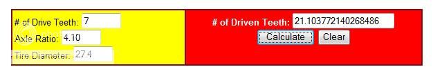
I bought the cherry 21 tooth driven gear. With a 21.1 calculated driven gear, I idea it would only exist a few miles off cruising simply actually when I'm doing lx it reads 80, 70 it reads 95-100, 90 it reads 120...

I pulled the cover and double checked the axle ratio, pulled out the speedo cable and double checked the driven gear, and that's definitely my tire size right at that place.

So, if anyone is running 4.10's with stock tires, what speedo gears do you take? I know roughly how fast I'm going by the rpm's, merely I would really like it to be accurate. Thanks guys

  • #2
The calculators are an estimation in my opinion.

It has been written that each tooth y'all add to the speedo driven gear will reduce the speedometer reading nearly 5%.

In my bodily feel, with the Muncie (which uses a similar mode gear, each tooth will modify the speedo reading by about 2 mph.

Your reading of lxx mph at around xc mph is a 37% error.

I would really have to doubtable your speedo head itself could be out of calibration.

Maybe Gauge marks will chime in....Robert

  • #3
77RS
... I would actually accept to suspect your speedo head itself could exist out of calibration.

Peradventure Guess marks will chime in....Robert


In that location are a lot of things to cistron in when changing tire sizes, gear ratios, etc... The most important thing is that the speedo is accurately calibrated before changing the driven gear. Was information technology accurate before the differential change?

The speedos in our cars are calibrated for grand turns per mile (Not to exist confused with engine RPMs). At 1000 turns of the speedo cable, the speedo should read threescore MPH. The original spec tolerance is +2/-ane. A change in the magnetism, distance betwixt the magnet and speed cup, trash in the mechanism, bushing gap, etc tin can crusade problems. Simply something to consider.

  • #4
vfw_1168
my speedo reads x mph off all the fourth dimension ... i am running a smaller tire as my rims offset is +19 with the stock tire i was rubbing the wheel well with those rims , then if i am doing sixty it reads 70 , with the stock wheels and tires it was 5 mph off lx was was doing 55 mph ... my tranny is the borg warner and the rear gears is the stock 3.42
  • #5
theflash
I have a th350 and 4.10 gears and 28" alpine tires also and IIRC my speedo gears are a 7/21 combo besides. My odometer is dead nuts to my gps, so I assume my speedo is correct as well. I would doubtable something else might exist the problem. Are you 100% sure you lot have the correct speedo gears past tooth count? Just going by the color is not 100% accurate. Also less likely, only worth asking, are you 100% sure y'all have iv.10's?
  • #6
Allow's kick this can one more time.

The goal of calibrating a speedometer is to get the drive to driven speedometer gear ratio.

Here's how to get to that end. Y'all need to know two pieces of data:

ane) You demand to know what the tire size is. Either the diameter or the size (similar 2.25/seventy/15).

2) You take to know the rear end gear ratio.

You and so plug that data into a speedometer reckoner. I prefer the one at Bowtie Overdrives: http://www.700r4.com/speedoCalc/speedocalc.shtml

Your information: 225/70R15 and four.ten gears gave a resultant of a 15 drive gear and a 45 driven gear. Separate 45 by xv = iii.000

At present become to this link that I posted here that has a chart on it to assistance you lot find the right drive and driven gears: http://www.nastyz28.com/forum/showthread.php?t=150376&highlight=speedometer

Scan the nautical chart and you will see that there are quite a few pairs of gears that will give you lot a 3.00 ratio: 7 & 21, 8 & 24, 9 & 27, 10 & 30, 11 & 33 and so on.

And so you demand to acquire the gears. I purchase mine from the local GM dealer mainly because I accept a "go to" counter person that knows HOW TO LOOK THEM Up!

Your's was an easy calculation. Just allow'due south say that the final gear ratio was an odd number like 2.589 . Browse my chart for numbers that are as close as y'all can to 2.589 . 7 & 18, 8 & 18 , 11 & 25 are just a few on that chart that will be close enought to make the speedometer authentic.

EDIT: I re-read your an everyone elses posts and agree that your speedometer head must be off. I've used the to a higher place method to calibrate MANY speedometers and establish information technology to be VERY accurate.

  • #vii
I didn't actually consider information technology before, just i recall you guys are right, the speedometer itself must be out of scale. I'm 110% certain near the info posted, then by process of elimination.. yeah. It's a 10+ yr former auto meter sport comp gauge. I plan on contacting auto meter and getting it re-calibrated. Recently I had them supplant a bulb in my tach (not-accessible type) information technology was only like $30 and they sent me basically a whole new estimate. Hopefully it's not much more than that, I'd rather not have to purchase a brand new unit.

Large thanks, some not bad info but got laid downward.. I retrieve this should do information technology.:happy:

Wink, I'm glad you mentioned that because now I KNOW something ain't right..

e-mailing autometer tomorrow for sure.

  • #eight
All these cutsie speedometer calculators on computers assume that your speedometer is authentic. That is a large mistake to assume.

The simplest way to become a speedometer right is the oldest way. You lot don't worry virtually gears, tire size, or any of that crap the calculators use to screw you upwardly.

All you need to know is how far your existing combination is off and in which direction. Then yous employ that percentage of fault and change gears past that percent. The old unproblematic way works 100% of the time, even if your speedometer has error in it. The new fangled stupid style of expecting a computer to figure it out for you gets yous just what you got...... Wrong.

Do it the old piece of cake style and get information technology right the first fourth dimension.

  • #9
77RS
Speedometer 101

Hope this will assistance clear up the understanding of how a speedo operates... :D

A speedometer is calibrated independently of the driven gears, etc. The driven gears (in the tranny) are used to friction match the driveline with a calibrated speedometer. There must be a constant, and so In our cars, the speedo is calibrated for k turns per mile. To figure the MPH at whatsoever given number of turns, multiply by .06 (ie: thousand x .06 = 60 MPH or 842 ten .06 = 51 MPH)

The speedometer works off of the magnetic field created by the turning magnet and the speed cup assembly. A modest change in the magnetism can cause huge differences in the speedo readings and accuracy.

The odometer works off of gears, so the odometer can exist completely accurate while the speedometer is xxx MPH off. I see it all the time.

A perfect example is that an 85 MPH speedo and a 150 MPH speedo is exactly the aforementioned unit of measurement (except for the '81 85 MPH). The divergence is in the magnetic field created by the rotating magnet and the speed cup assembly. I can recalibrate an 85 MPH to exist a 150 mph by changing the magnetism and of form, the speedo confront. (This takes specialized equipment, so don't try this at home ;) ) All of these speedos use the same odometer.

A MPH speedo can exist converted to a KPH speedo by changing the magnetic field. To change the odometer to read kilometers instead of miles, the tertiary worm gear has to exist inverse. Although a speedo and odometer are in the aforementioned housing, their operation is actually independent of each other.

Promise this helps!
Daniel

Last edited:
  • #10
Thanks! That was actually really helpful. I had no idea there was that much going on in there.

AND, plain niether does the guy I merely talked to at AutoMeter. He's telling me that the mechanical speedometer is calibrated simply by the gears in the trans.. ??? I said no, I retrieve it's a little more complicated than that, he said no it's about as simple a device as can be.. Gave me a # for i of their buddy companies that sold speedo cables and gears and possibly they could help me. :mad: He basically told me there was no calibration necessary on a mech speedo, it but works. And so what the hell...

-The speedo I'k using is a mechanical Sport-Comp 3992. I got information technology used only it's probably around 12 years sometime.

  • Forums
  • Drivetrain & Operation
  • Transmission & Driveline Topics

DOWNLOAD HERE

Speedometer Calibration How Many Mph Does One Speedo Gear Tooth Make UPDATED

Posted by: pearliebild1951.blogspot.com

How to Draw a Gas Riser Diagram TUTORIAL

plumbing riser diagram

What Are Plumbing Riser Diagrams?

Showtime of all, information technology is of import to understand what risers are. In essence, they are pipes, but very specific pipes.

In the movie on the left, y'all can encounter a large waste pipe, and the common cold and hot water supply pipes (marked blueish and crimson respectively) leading to the position of the sink, indicated by a line drawing. The position of all of these, and all other relevant pipe, will be shown on a riser diagram. However, only the water supply pipage is really a riser.

The New York City (NYC) Plumbing Code defines risers as water pipes that extend one full story or more and convey h2o to a grouping of fixtures (like baths, sinks, showers, and lavatories) or to branches that extend to fixtures on two or fewer sequent floors. Branches do non include risers, mains water pipes, or stacks, the latter of which are vertical lines of soil (for sewage), waste (water from fixtures and appliances, commonly called gray water), vents (to get rid of harmful gases), or inside conductor piping (for storm water).

Withal, it isn't merely risers that are included in plumbing riser diagrams, as yous can see in Design of Plumbing Systems beneath. For example, the NYC Department of Building (DOB) requires stacks to be shown on plumbing riser diagrams even though they are not risers! Then too does the NYC Plumbing Code.

The indicate of a plumbing riser diagram is to separate out plumbing systems for drink h2o, waste h2o, storm h2o, sewage, and and so on to be able to place exactly where the different pipe is located and what it is attached to in terms of appliances, drains, other edifice systems, and so on.

A plumber riser diagram is not necessarily drawn to scale, but information technology must be accurate enough to clearly show the concept. It is ofttimes created every bit a 2D diagram rather than an isometric 3D or an even more complicated axiomatic drawing.

What it needs to show is how the risers and various other pipes relate to one another and to fixtures, drains, traps, and valves or taps, simply with just a series of lines. Water and waste matter pipes are shown as solid lines while vents are shown every bit dotted lines.

Design of Plumbing Systems

Drawings  for plumbing riser diagrams

The NYC DOB has guidelines for the "pattern professional person requirements" for plumbing projects in the urban center. Commencement and foremost, it is essential for a state-licensed engineer, such as the highly experienced engineers who piece of work for Nearby Engineers New York Engineers , or builder to submit work permit applications and the plans required for the project to the DOB. For all plumbing installation and modification projects, engineers and architects are encouraged to submit project applications that have been professionally certified to show that they have been completed in accordance with the relevant codes and other legislation.

From July 2019, all permit requests and plumbing chore filings have to be submitted via DOB Now, a new online tool that has been introduced to simplify business dealing with the DOB. Even though the DOB already has an eFiling organisation in place, from July 2019, no paper filings volition be accepted.

The NYC DOB provides useful information that will help all non-professionals understand the wide range of construction documents required for both new builds and alterations/modifications. Riser diagrams are, of course, mentioned along with the usual site and floor plans, as well equally detail drawings, and an free energy analysis. Substantially, if any new piping is to be installed a riser diagram is required to prove the details for:

  • Stacks, which include germ-free, tempest, and vent pipe.
  • Both hot and common cold main water supply lines.
  • Sprinklers off domestic, standpipe, and gas supply pipage.

Elevations across floors must also exist indicated.

In terms of the codes that legislate plumbing design (including plumbing riser diagrams), while the NYC Building Code has a chapter on plumbing systems, all this states is that the NYC Plumbing Code governs the "construction, erection, installation, alteration, repairs, relocation, replacement, addition to, utilise or maintenance of plumbing equipment and systems."

And so, it is the Plumbing Code that we, as MEP engineers, refer to for mandatory requirements for structure documents of diverse kinds required for building permits. The Code requires very specific information and information from construction plans and you will meet that the plumbing riser diagram is only one of the v listed below:

  • Riser diagrams that evidence the heights of stories, all plumbing equipment and the diagrammatic arrangement of their connections to soil, waste material, and vent piping. All soil, waste, and vent stacks must be included in the diagram showing their bespeak of connection with the building bleed to where they stop to a higher place the roof. Also, all leader piping used to drain tempest water from the roof or gutter drains, and storm water piping from the point of connection with the edifice bleed to the roof bleed must be shown. Last but not to the lowest degree, all risers must be shown on the plumbing riser diagram.
  • Diagrammatic floor plans that show the layout, location, and spacing of plumbing fixtures as well as plumbing loads and the size, textile, and location of and for edifice sewers, drains. Water, waste, soil, vent, and gas distribution pipage must also be shown. And so in that location is some overlap between these plans and riser diagrams, but their presentation is different.
  • Floor plans that indicate layouts with stack details shown on i drawing.
  • Plans for appurtenant equipment including water tanks, pumps, ejectors, and piping.
  • Plans for new plumbing systems and alterations of existing systems. In addition to showing the relevant tiptop of the lowest fixture and the approximate within superlative of public sewers, these must testify the number, size, and location of proposed sewer connections also as the size and relative location of all water mains, leaders, and risers. A statement from the Department of Environmental Protection giving the minimum water pressure in the main that serves the building is besides required.

Of form, the Plumbing Code likewise has comprehensive details relating to the design of building h2o distribution systems, sanitary drainage, storm drainage, and vents, all of which are relevant to plumbing riser diagrams.

Annotation that while fire sprinklers off domestic, standpipe, and gas supply piping are mentioned in the DOB guidelines, they are not regulated by the NYC Plumbing Code only rather by the NYC Fire Code and the NYC Building Code. However, the specifications are that sprinkler systems should be designed and installed in accord with National Fire Protection Association (NFPA) standards, particularly:

  • NFPA 13: Standard for the Installation of Sprinkler Systems
  • NFPA 13D: Standard for the Installation of Sprinkler Systems in One- and Two-Family Dwellings and Manufactured Homes
  • NFPA 13E: Recommended Do for Fire Department Operations in Properties Protected past Sprinkler and Standpipe Systems
  • NFPA 13R: Standard for the Installation of Sprinkler Systems in Low-Rise Residential Occupancies
  • NFPA 25: Standard for the Inspection, Testing, and Maintenance of H2o-Based Burn down Protection Systems

Even though plumbing riser diagrams for buildings tin can incorporate water supply and waste matter h2o, tempest water, and sewage, plumbing systems in large, high-rise buildings are complex and so these ii broad elements are quite often separated into two riser diagrams. If at that place is a sprinkler system, this may likewise be shown in a separate riser diagram. For this reason, we will discuss the different elements separately.

DOWNLOAD HERE

How to Draw a Gas Riser Diagram TUTORIAL

Posted by: pearliebild1951.blogspot.com

How to Draw a Dragon Art Hub for Kids TUTORIAL

Drawing A Drawing Dragon

by Dawn 145 0% i 0

Drawing Saber From Fate Nada

by Dawn 220 0% 0 1

Drawing Lovers, Orbital Lovers

by Dawn 784 0% 0 0

How To Describe Goth

past Dawn 1k 100% 0 2

How To Draw Iii Blind Mice

past Dawn 504 100% ane 0

How To Describe A Rattlesnake

by Dawn 643 100% 0 0

How To Draw A Sleeping Moon

by Dawn 626 0% 0 0

Draw A Warrior Wolf

by Dawn 1k 0% 0 0

How To Draw Low-cal Fury

by Dawn 556 0% 0 0

Draw A Behave

by Dawn 1k 0% 1 one

How To Draw Surfer Waves, Wave ...

by Dawn 460 0% 0 0

How To Draw A Cartoon Demon

by Dawn 725 100% 0 1

How To Draw Ultra Instinct Gok ...

by Dawn 1k 0% 0 0

How To Draw Mike From Stranger ...

by Dawn 364 0% 0 0

How To Depict Hopper From Strang ...

by Dawn 313 0% 0 0

How To Draw Lynx From Fortnite

by Dawn 1k 100% 0 1

How To Describe Halsey

by Dawn 616 0% 0 0

How To Draw Momo

by Dawn 1k 0% 0 0

How To Draw Chibi C-3po

past Dawn 564 0% 0 0

How To Draw Chibi Princess Lei ...

by Dawn 511 0% 0 0

Draw Old Luke Skywalker Chibi ...

by Dawn 710 100% 3 0

Depict Mamá Imelda From Coco

past Dawn 583 0% 0 0

How To Draw Dustin From Strang ...

by Dawn 595 0% 0 0

How To Depict Zamazenta

by Dawn 692 0% 0 1

DOWNLOAD HERE

How to Draw a Dragon Art Hub for Kids TUTORIAL

Posted by: pearliebild1951.blogspot.com