What Are Plumbing Riser Diagrams? Showtime of all, information technology is of import to understand what risers are. In essence, they are pipes, but very specific pipes. In the movie on the left, y'all can encounter a large waste pipe, and the common cold and hot water supply pipes (marked blueish and crimson respectively) leading to the position of the sink, indicated by a line drawing. The position of all of these, and all other relevant pipe, will be shown on a riser diagram. However, only the water supply pipage is really a riser. The New York City (NYC) Plumbing Code defines risers as water pipes that extend one full story or more and convey h2o to a grouping of fixtures (like baths, sinks, showers, and lavatories) or to branches that extend to fixtures on two or fewer sequent floors. Branches do non include risers, mains water pipes, or stacks, the latter of which are vertical lines of soil (for sewage), waste (water from fixtures and appliances, commonly called gray water), vents (to get rid of harmful gases), or inside conductor piping (for storm water). Withal, it isn't merely risers that are included in plumbing riser diagrams, as yous can see in Design of Plumbing Systems beneath. For example, the NYC Department of Building (DOB) requires stacks to be shown on plumbing riser diagrams even though they are not risers! Then too does the NYC Plumbing Code. The indicate of a plumbing riser diagram is to separate out plumbing systems for drink h2o, waste h2o, storm h2o, sewage, and and so on to be able to place exactly where the different pipe is located and what it is attached to in terms of appliances, drains, other edifice systems, and so on. A plumber riser diagram is not necessarily drawn to scale, but information technology must be accurate enough to clearly show the concept. It is ofttimes created every bit a 2D diagram rather than an isometric 3D or an even more complicated axiomatic drawing. What it needs to show is how the risers and various other pipes relate to one another and to fixtures, drains, traps, and valves or taps, simply with just a series of lines. Water and waste matter pipes are shown as solid lines while vents are shown every bit dotted lines. Design of Plumbing Systems The NYC DOB has guidelines for the "pattern professional person requirements" for plumbing projects in the urban center. Commencement and foremost, it is essential for a state-licensed engineer, such as the highly experienced engineers who piece of work for Nearby Engineers New York Engineers , or builder to submit work permit applications and the plans required for the project to the DOB. For all plumbing installation and modification projects, engineers and architects are encouraged to submit project applications that have been professionally certified to show that they have been completed in accordance with the relevant codes and other legislation. From July 2019, all permit requests and plumbing chore filings have to be submitted via DOB Now, a new online tool that has been introduced to simplify business dealing with the DOB. Even though the DOB already has an eFiling organisation in place, from July 2019, no paper filings volition be accepted. The NYC DOB provides useful information that will help all non-professionals understand the wide range of construction documents required for both new builds and alterations/modifications. Riser diagrams are, of course, mentioned along with the usual site and floor plans, as well equally detail drawings, and an free energy analysis. Substantially, if any new piping is to be installed a riser diagram is required to prove the details for: Elevations across floors must also exist indicated. In terms of the codes that legislate plumbing design (including plumbing riser diagrams), while the NYC Building Code has a chapter on plumbing systems, all this states is that the NYC Plumbing Code governs the "construction, erection, installation, alteration, repairs, relocation, replacement, addition to, utilise or maintenance of plumbing equipment and systems." And so, it is the Plumbing Code that we, as MEP engineers, refer to for mandatory requirements for structure documents of diverse kinds required for building permits. The Code requires very specific information and information from construction plans and you will meet that the plumbing riser diagram is only one of the v listed below: Of form, the Plumbing Code likewise has comprehensive details relating to the design of building h2o distribution systems, sanitary drainage, storm drainage, and vents, all of which are relevant to plumbing riser diagrams. Annotation that while fire sprinklers off domestic, standpipe, and gas supply piping are mentioned in the DOB guidelines, they are not regulated by the NYC Plumbing Code only rather by the NYC Fire Code and the NYC Building Code. However, the specifications are that sprinkler systems should be designed and installed in accord with National Fire Protection Association (NFPA) standards, particularly: Even though plumbing riser diagrams for buildings tin can incorporate water supply and waste matter h2o, tempest water, and sewage, plumbing systems in large, high-rise buildings are complex and so these ii broad elements are quite often separated into two riser diagrams. If at that place is a sprinkler system, this may likewise be shown in a separate riser diagram. For this reason, we will discuss the different elements separately.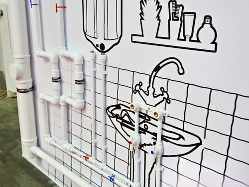
DOWNLOAD HERE
How to Draw a Gas Riser Diagram TUTORIAL
Posted by: pearliebild1951.blogspot.com
How to Draw a Gas Riser Diagram TUTORIAL. There are any How to Draw a Gas Riser Diagram TUTORIAL in here.

